Key Factors to Consider When Using Cylinder Lenses
Feb. 01, 2025
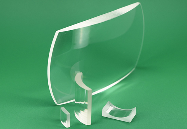
Cylinder lenses, like spherical lenses, use curved surfaces to converge or diverge light. However, they have optical power in only one dimension, affecting light in just that direction, while leaving the perpendicular dimension unchanged. This is not possible with spherical lenses, which cause light to focus or diverge symmetrically in all directions. Cylinder lenses are crucial in manipulating and shaping laser light, used for creating laser light sheets and circularizing elliptical beams. Given their asymmetric nature and the specialized manufacturing processes involved, it's essential to carefully control the centration, wedge, and axial twist.
Cylinder lenses require specialized equipment and expertise for manufacturing, along with a unique coordinate system to reference lens features. The reference system is defined by two orthogonal directions: the power direction and the non-power direction. The power direction runs along the curved length of the lens and is the only axis with optical power. The non-power direction runs along the lens without any optical power, allowing the lens to extend in this direction without affecting its optical properties. Cylinder lenses come in various form factors, including rectangular, square, circular, and elliptical shapes.
Errors, Aberrations, and Specifications
No manufacturing process is free from imperfections, and cylinder lens production is no exception, making small geometric errors inevitable. Misalignment during polishing can introduce mechanical errors specific to cylinder lenses, resulting in optical aberrations that negatively impact performance. To ensure optimal lens function, these errors must be carefully controlled. They are defined relative to geometric datums, such as the planar side and edges of the lens.
Wedge
In an ideal cylinder lens, the planar side is parallel to the cylinder axis. Any angular deviation between the planar side and the cylinder axis is known as the wedge, typically measured in arcminutes. This angle is determined by comparing the thicknesses at both ends of the lens. Wedge leads to an image shift in the non-power direction, similar to the effect of wedge in a window.
Centration
In an ideal cylinder lens, the optical axis of the curved surface is parallel to the lens edges. Similar to the decentering of a spherical optic, the centration error of a cylinder lens is the angular deviation of the optical axis from the lens edges. This centration angle (α) causes the optical and mechanical axes to become misaligned, leading to beam deviation. If the lens edges are used as a mounting reference, this error can complicate optical alignment. However, if the edges are not relied upon for mounting, the error can be corrected by decentering the lens appropriately. For larger diameter cylinder lenses, the edge thickness difference increases for a given centration angle.
Axial Twist
Axial twist refers to the angular deviation between the cylinder axis and the lens edges, representing a rotation of the powered surface relative to the outer dimensions of the lens. This twist causes the image to rotate around the optical plane. Axial twist can be problematic when rectangular elements are mounted by their outer dimensions. To counteract this, rotating the lens to realign the cylinder axis can help correct the issue.
Applications
Cylinder lenses are primarily used in laser beam shaping to correct asymmetric beams, create a line, or generate a light sheet. Modern scientific techniques, such as Particle Image Velocimetry (PIV) and Laser Induced Fluorescence (LIF), often rely on a thin laser line or an even laser light sheet. Structured laser light is also crucial for scanning, measurement, and alignment applications. With the availability of low-cost laser diodes, another common use is circularizing the elliptical output from a diode to produce a collimated, symmetric beam.
Forming a Light Sheet
A light sheet is a beam that diverges along both the X and Y axes. It includes a rectangular field that is orthogonal to the optical axis, expanding as the propagation distance increases. A laser line formed using a cylinder lens can also be viewed as a light sheet, although it has a triangular shape and extends along the optical axis.
To create a true laser light sheet with divergence in both axes, a pair of convex or concave cylinder lenses, oriented orthogonally to each other, is required. Each lens affects one axis, and together, they produce a diverging sheet of light.
Circularizing a Beam
A laser diode without collimating optics will produce an asymmetrical divergence. A spherical optic cannot create a circular collimated beam, as it affects both axes simultaneously, preserving the original asymmetry. An orthogonal pair of cylinder lenses addresses this by treating each axis separately.
To achieve a symmetrical output beam, the ratio of the focal lengths of the two cylinder lenses should match the ratio of the X and Y beam divergences. Similar to standard collimation, the diode is placed at the focal point of both lenses, and the distance between the lenses corresponds to the difference in their focal lengths.
Laser diodes often exhibit a large divergence, which presents a challenge in collimating. Divergence directly impacts the system's length and the required size of the lenses. Since the relative positions of each component are largely fixed by their focal lengths, the maximum beam width (d) at each lens can be calculated using the lens's focal length (f) and the divergence angle (θ) of the axis being collimated. The clear aperture of each lens must then be larger than the calculated maximum beam width.


