Key term and meaning of optical filters
Apr. 09, 2024
Know about key term of optical filters
Center Wavelength
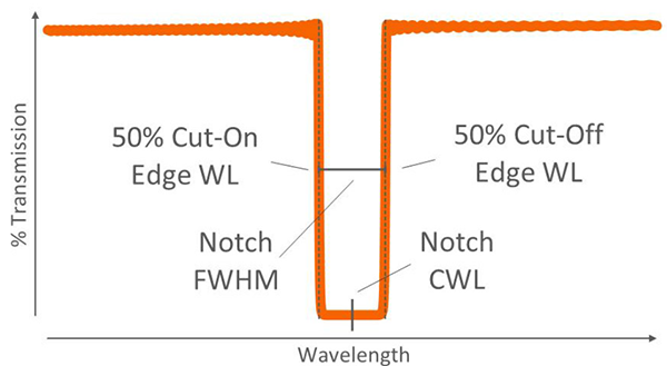
The center wavelength (CWL) can be used to describe the passband center or trap center. The center wavelength is defined as the midpoint or average between two
adjacent conduction and cutoff wavelengths.
2. Full width at half peak (FWHM) and bandwidth
The full width at half maxima(FWHM) is the distance between two neighboring 50% edge points, also known as the 50% bandwidth of a bandpass or trap filter. Bandwidth is a broader term that is not limited to 50% of peak transmittance and can be expressed as an absolute value or percentage of peak transmittance. For example, a common specification is bandwidth at 80% of peak, or 10% of absolute bandwidth.
3. Cut-On and Cut-Off Wavelength
Cut-On and Cut-Off Wavelength describe the edge transition of the optical filter. The start wavelength is used to indicate a sharp increase in transmittance over a range of wavelengths, as in the case of long-pass filters. Conversely, the cutoff wavelength describes an edge transition where the transmittance decreases over a certain wavelength range, such as in short-pass filters. They are defined as the point at which transmission peaks at 50% on their respective edges, and are also referred to as the 50% edge point and half-power wavelength.
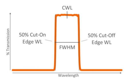
As with the center wavelength and half-peak full width below, the start and cutoff wavelengths can be specified as either nominal wavelength or ± wavelength tolerance. In cases where dichroic filters are specified using the average polarization, the average wavelengths corresponding to 80% and 20% of the peak transmittance are usually used to evaluate the start and cutoff wavelengths. This is because deviations due to polarization splitting usually occur around the 50% fringe point.
4. Transmittance, reflectance and blocking bands
Transmission bands, reflection bands, and blocking bands are spectral regions where each property must be above, below, or within a certain level. Typically, the transmittance of 0° AOI filters (e.g., long-pass or short-pass edge filters, band-pass filters, and trap filters) is expressed as a percentage, and the blocking is measured in optical density (OD).
OD=-log10(T)
OD = optical density
T = transmittance (0 ≤ T ≤ 1)
Blocking is a generic term that refers to the attenuation of a beam of light of a specific wavelength by reflectance, absorbance, or both. For most 0° AOI filters, the attenuated beam does not enter another path in the system, so it is not necessary to specify reflectance. However, most filters and coatings used at larger angles of incidence, such as dichroic filters and high reflectance (HR) mirrors, are designed to split or reflect the beam within the system, so these filters and coatings must be specified for reflective bands, not blocking bands.
When specifying transmission bands, blocking bands, and reflection bands, it is important to specify whether the specification is an absolute or an averaging specification. For example, an average transmission band specification means that the average transmission values over the specified wavelength range must satisfy the specified tolerance (e.g., Tavg > 95%). An absolute transmission specification, on the other hand, means that all transmitted values in the specified range must meet the tolerance (e.g., Tabs > 95%).
Some systems and applications mandate absolute specifications, but this may result in increased cost or reduced design feasibility if the transition between the transmission band and the blocking/reflecting band is tight. To maintain design feasibility, edge transitions, AOI ranges, CHA and manufacturing tolerances should also be considered when determining transmission, blocking and reflection ranges.
5. Ripple effect
The ripple effect is the theoretical and measured amount of permissible variation within the transmitted or reflected band, often referred to as peaks and valleys (e.g. Tripple < 5% P-V). Filters with too much or too little transmission or reflection ripple can degrade the performance of certain systems. For example, emission filters with moderate passband ripple in fluorescence imaging systems can result in reduced image contrast. Therefore, optical filter manufacturers should design filters with low passband ripple and maintain precise control during the coating process to minimize ripple. This is a good practice even if ripple is not specified.
6. Edge steepness
Edge steepness is the sharpness of the transition between the transmission band and the neighboring blocking or reflecting bands. It can be specified as a distance (e.g. λ90%T to λOD2 < 5 nm) or as a percentage (λ50%T to λOD4 < 1% of edge WL). When this specification is used with averaged transmission bands and blocking/reflection bands, it is useful to hint at edge steepness. However, this is generally not necessary if the transition between adjacent bands is tight, or when both bands are specified as absolute. In these cases, the steepness of the filter is already determined by the transmission and blocking/reflection specifications.
7. Anti-Reflective Coating
Anti-Reflective (AR) coatings provide high transmittance and low reflectance in the specific wavelength range required by the system. The common purpose of coating various optical elements is to increase transmittance and eliminate any ghosting caused by backward reflected light in the system. One or more surfaces of an optical element can be coated with AR.
For optical interference filters designed with the primary coating on a single surface, such as trap filters, long-pass filters, short-pass filters, dichroic filters, and some band-pass filters, an AR coating must be applied to the second surface of the substrate to minimize transmission losses due to Fresnel reflections.
For many other bandpass filters, multi-band filters, and thick optical coatings, the coating designer must split the coating between the two surfaces to mitigate the effects of coating stress. In these cases, the second side coating is always designed to have a high transmittance and low reflectance region corresponding to the specified transmission band, thus minimizing Fresnel reflections and effectively acting as an AR coating. However, if the system requires very low values of AR reflectivity on the second side, the second-side AR coating is still necessary.
CLZ Optical Co., Ltd. is a manufacturer of optical components, main products including spherical lenses, optical domes, windows, filters, mirrors, etc. Our product are widely use in various fields, such as Lasers, medical, imaging systems, aerospace, underwater photography, etc. We also could provide OEM service.
Please contact us free time if you have any needs.
Previous: Infrared Thermal Imaging Camera


